1970s Projects
Click on images to view a high-resolution version in the Harvard Viewer
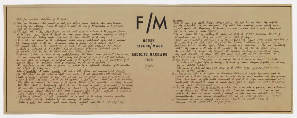
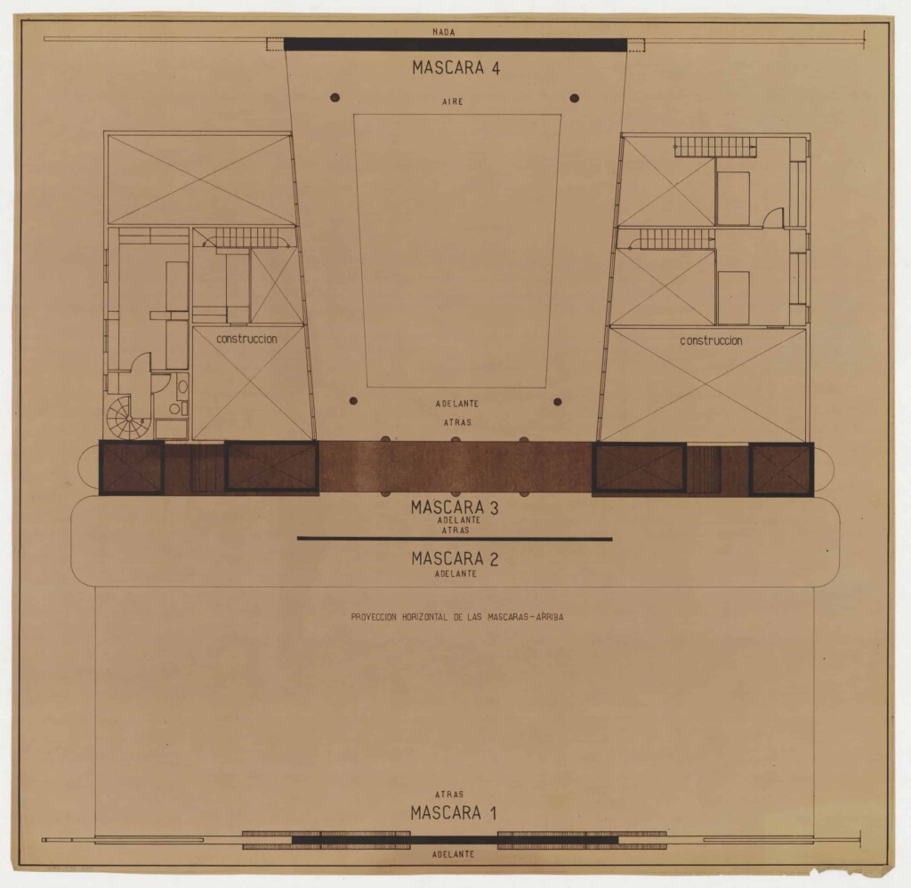
Facade/mask house [1972]
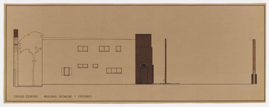
This house was designed to be built in the outskirts of Cuernavaca, Mexico. It is an experimental project in the transformation of a local house type (characterized by two parallel wings, connected with a gallery that encloses a patio) through the exploration of the opposition façade/mask. It discusses the difference between architecture and construction, understood as distinct modes of production; and the facade as an element of architecture established by classical and modern notions of unicity, planarity, layering, limit, entrance, frontality and axiality.
The original drawings, exhibited at the Museum of Modern Art in 1975, take the format of a triptych, with the masks (and text discussing the house) as the central panel, first floor at left, and second floor at right. The different pieces are ordered following a traditional format of a triptych: an articulated plane characterized by closing upon itself, but in this case the reverse side of the triptych is not used. Once it is closed the representation can be put aside.
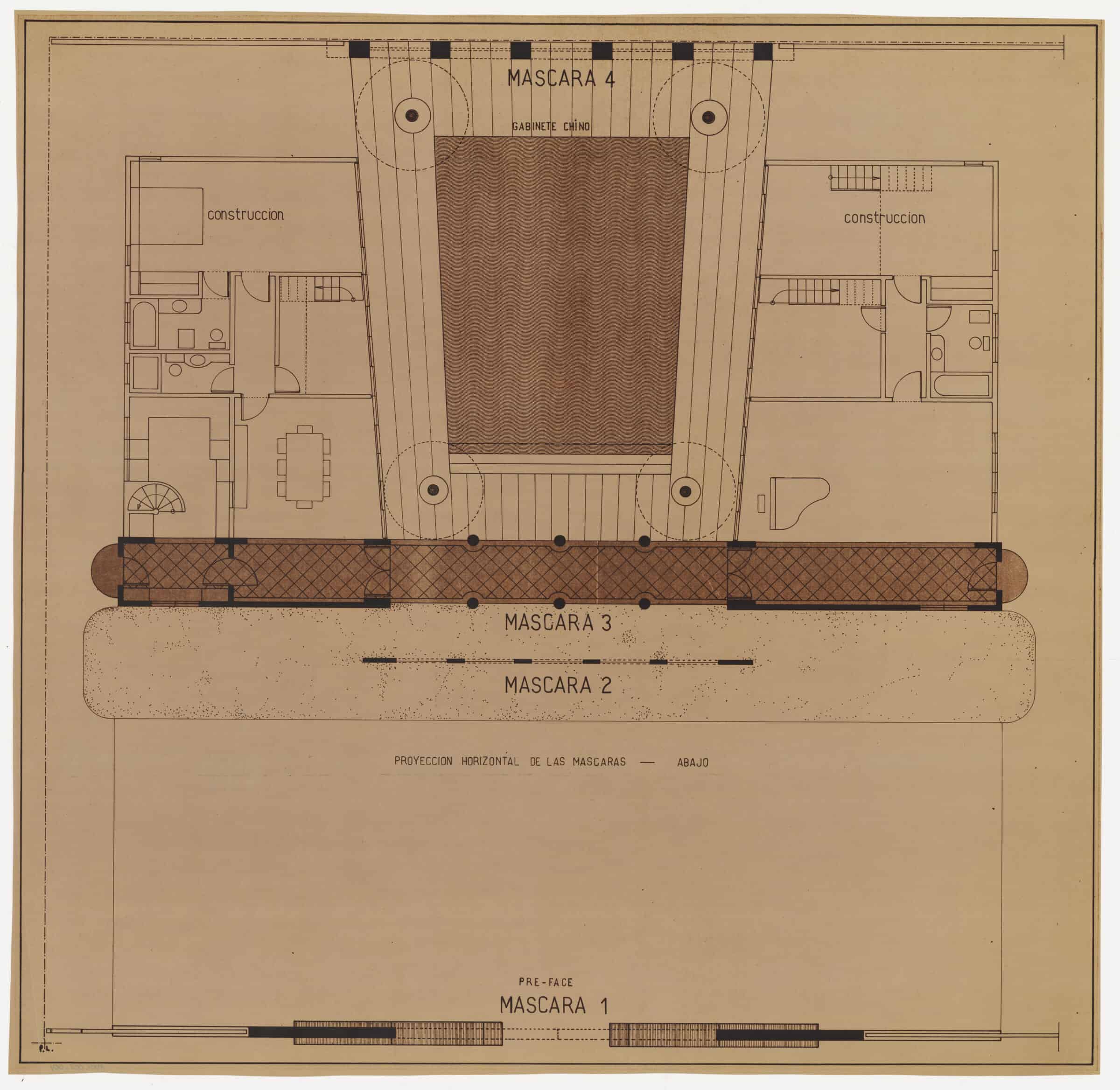

Floor Plan One (diazotype; 25″ x 25 1/2″)
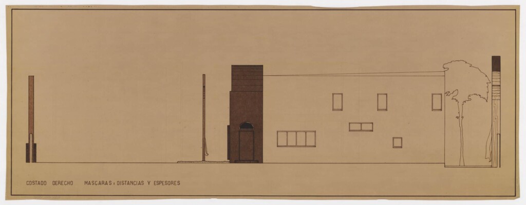
Left Side Elevation (diazotype; 25 1/2″ x 9 3/4″)
Back Facade with Hidden Masks (diazotype; 25 1/2″ x 9 3/4″)
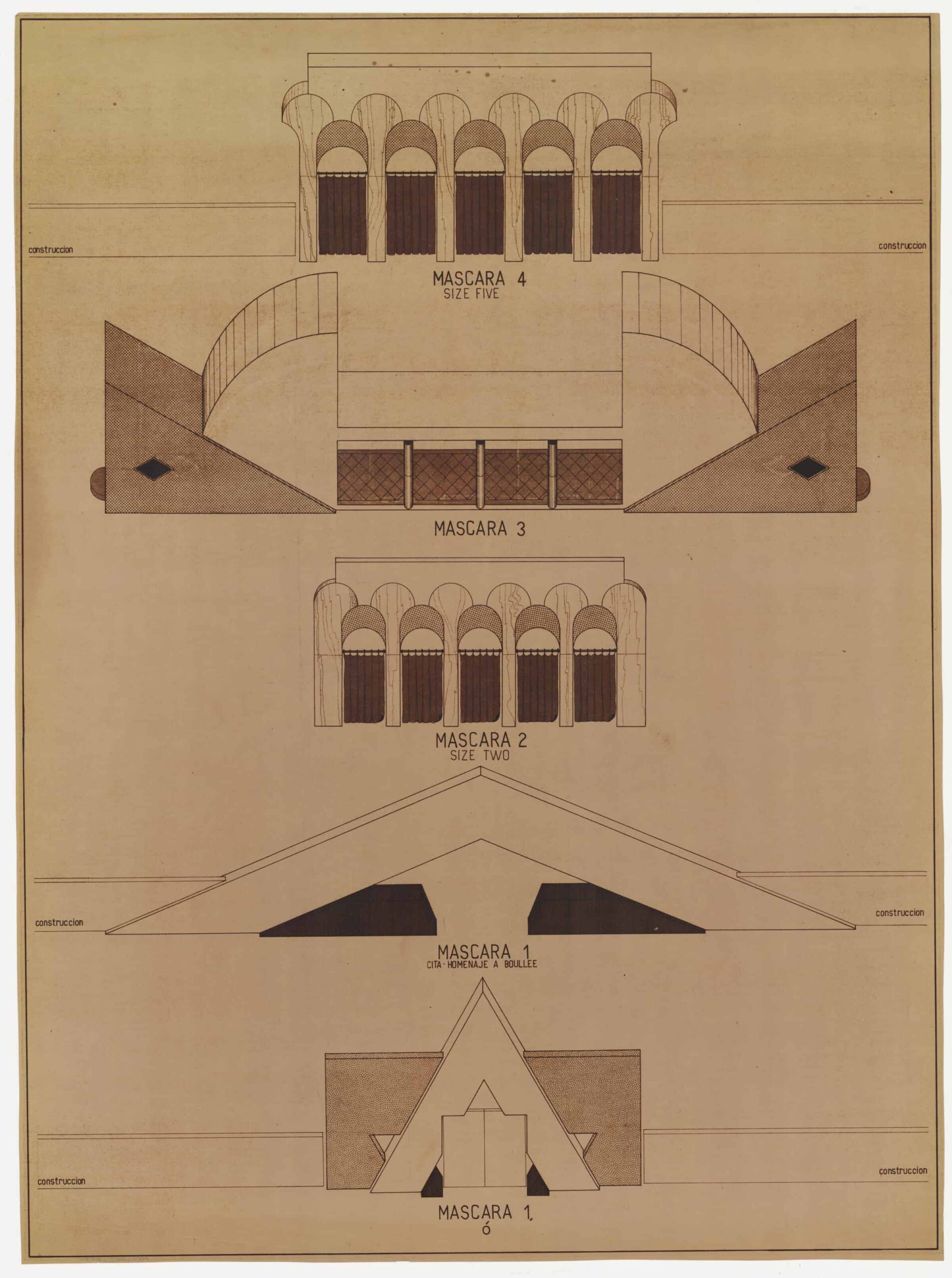
Four Elevations (diazotype; 25 1/2″ x 34″)
Notes for Possible Description (diazotype; 9 3/4″ x 25″)
Floor Plan 2 (diazotype; 25″ x 25 1/2″)
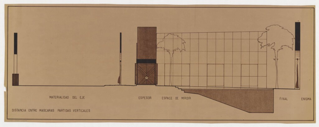
Right Side Section (diazotype; 25 1/2″ x 9 3/4″)
Back Facade with Hidden Masks (diazotype; 25 1/2″ x 9 3/4″)
ROOSEVELT ISLAND HOUSING [1975]
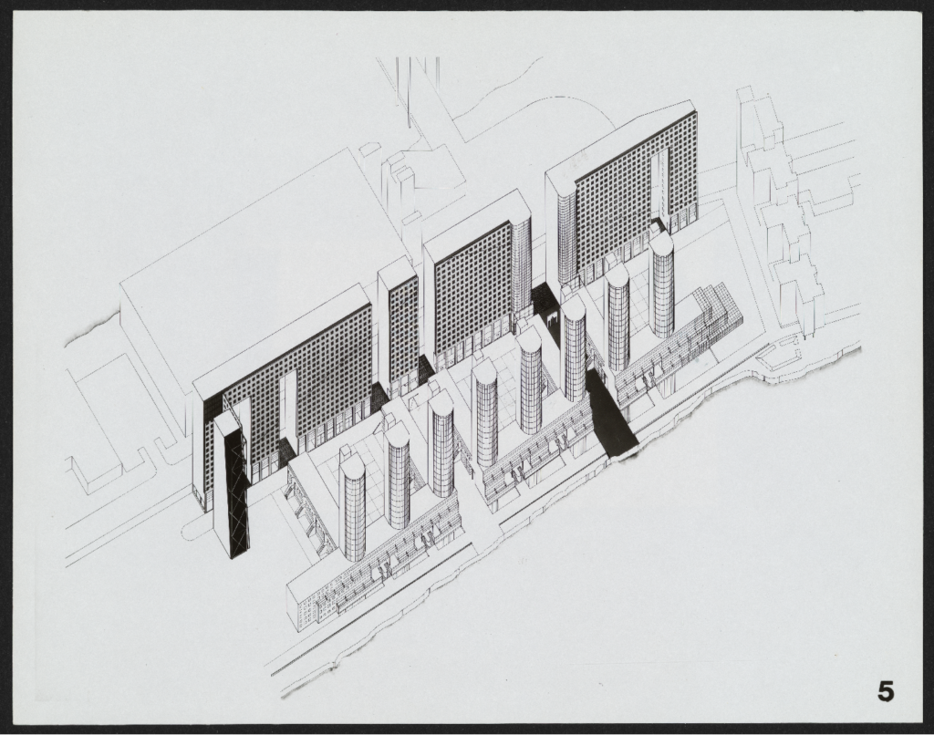
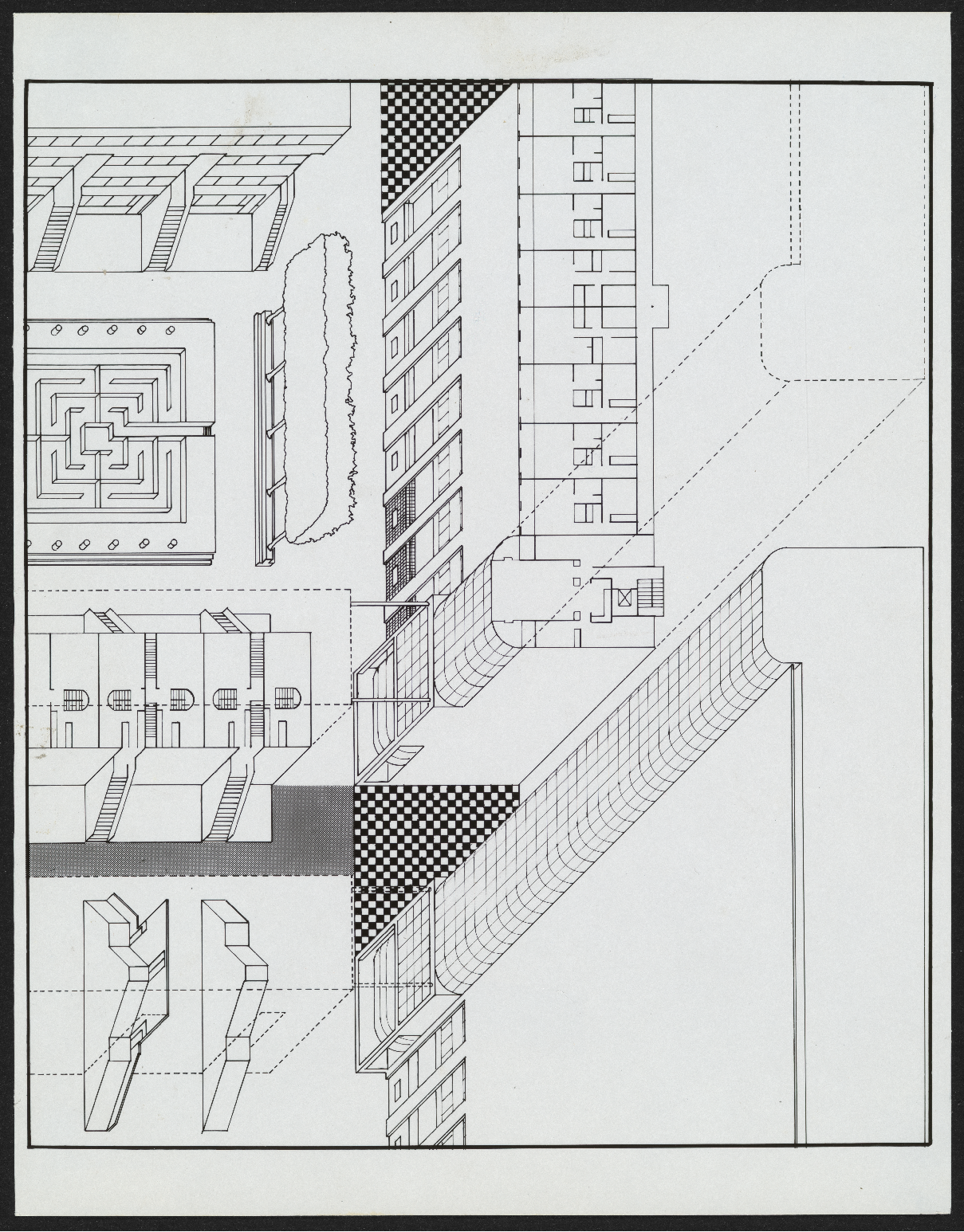
Entry for the Roosevelt Island Housing Competition (in association with Diana Agrest and Mario Gandelsonas). The competition was treated as a pretext to pose a series of questions concerning the housing problem, and to consider it as part of the more general work of reflection on architecture and the production of meaning in building design and construction. Instead of the traditional alternatives of “housing as monument” versus “housing as a symbolically neuter construction”, the proposal offers housing to be thought of as one of the dominant symbolic entities of the constructed world. This approach to the housing problem is possible on the condition that architectural ideology be shifted toward a newer problem in which design and reading, as functions of production and transformation of significance of the constructed world, play a fundamental role.
In design, these operations are closer to transcription, juxtaposition, and transformation rather than to invention. Transcription transfers existing typologies (the townhouses, the towers). Juxtaposition appears in a logic system in which the fragments act as neuter elements (and public spaces act as the linkage to those fragments). Transformation allows the creation of elements that add new meaning to the original meaning. Examples of this process are apparent in the transformation of towers into colonnades, or of the high-rises into walls.
Regarding reading, the design attempts to include clues to allow for the consideration of an alternative to the traditional concept of meaning in architecture. Instead of a single meaning (a content inherent to the object) it would now be completely metaphorical: some level of variation on the traditional restrictions of meaning. Therefore, elements would exist that “transcend” the single sense, opening it to others. One such element is the tower which is detached from the wall and exposes the structure, it is one of the elements that opens up the reading of “housing as a temple” to the city.
A dialogue is then created between monument and city, architecture and housing, where housing can even be read as mega-monument and therefore recovers it as architecture and not merely programmatic construction. This urban architecture of towers, walls, and streets is now added to the formal structures originating in modern and classical architecture.

Site Plan and Axonometric (photographic print, 8″ x 10″)

Axonometric (photographic print, 8″ x 10″)
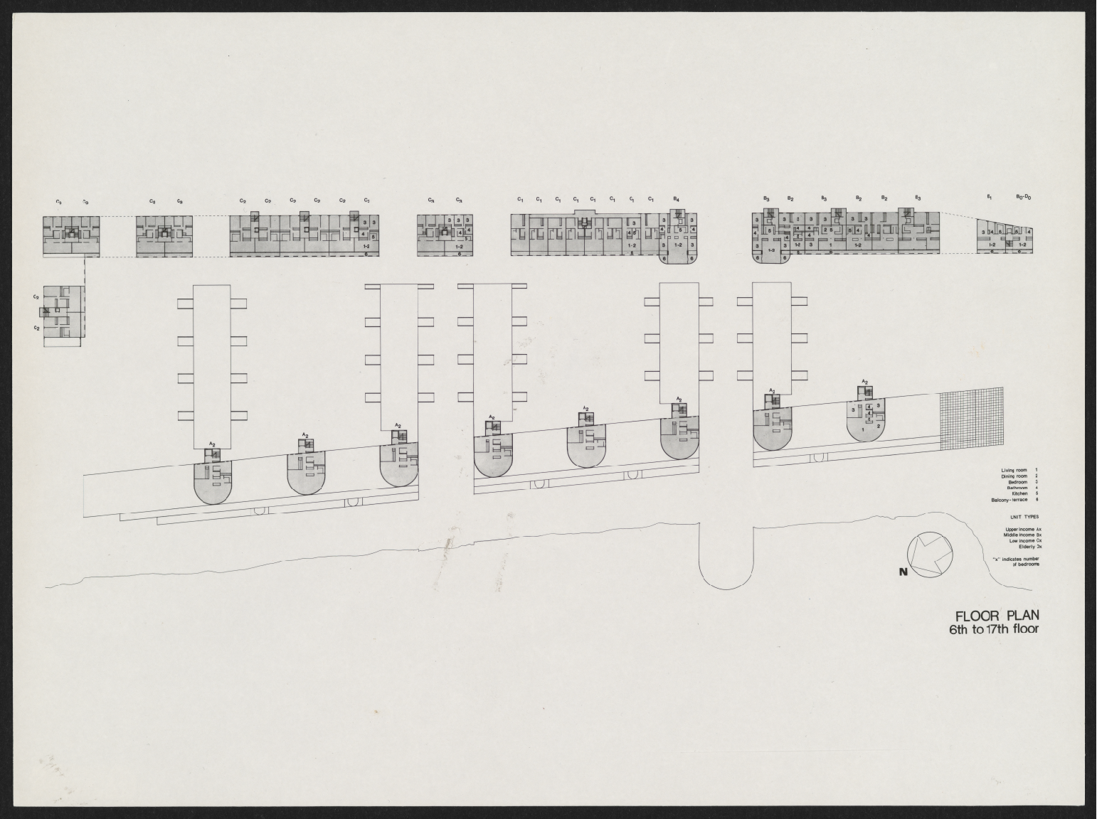
6th to 17th Floor [Floor Plan] (photographic print, 8″ x 10″)
Axonometric (photographic print, 8″ x 10″)
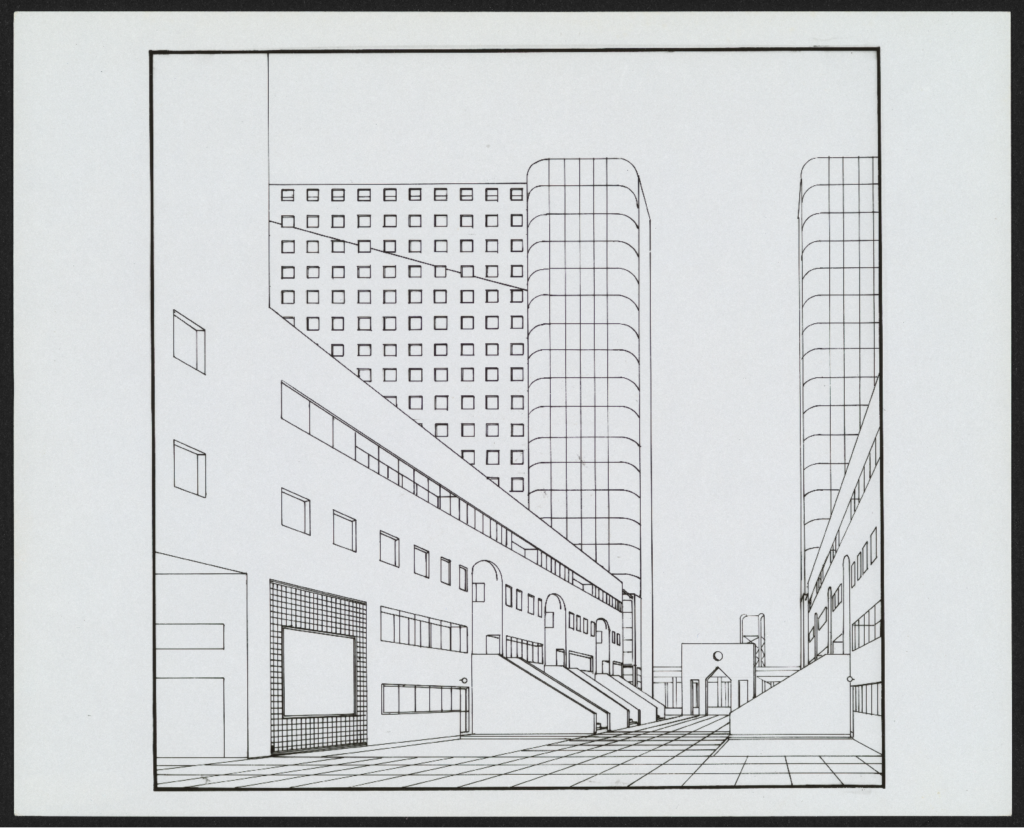
Exterior Perspective 01 (photographic print, 8″ x 10″)

Exterior Perspective 02 (photographic print, 8″ x 10″)
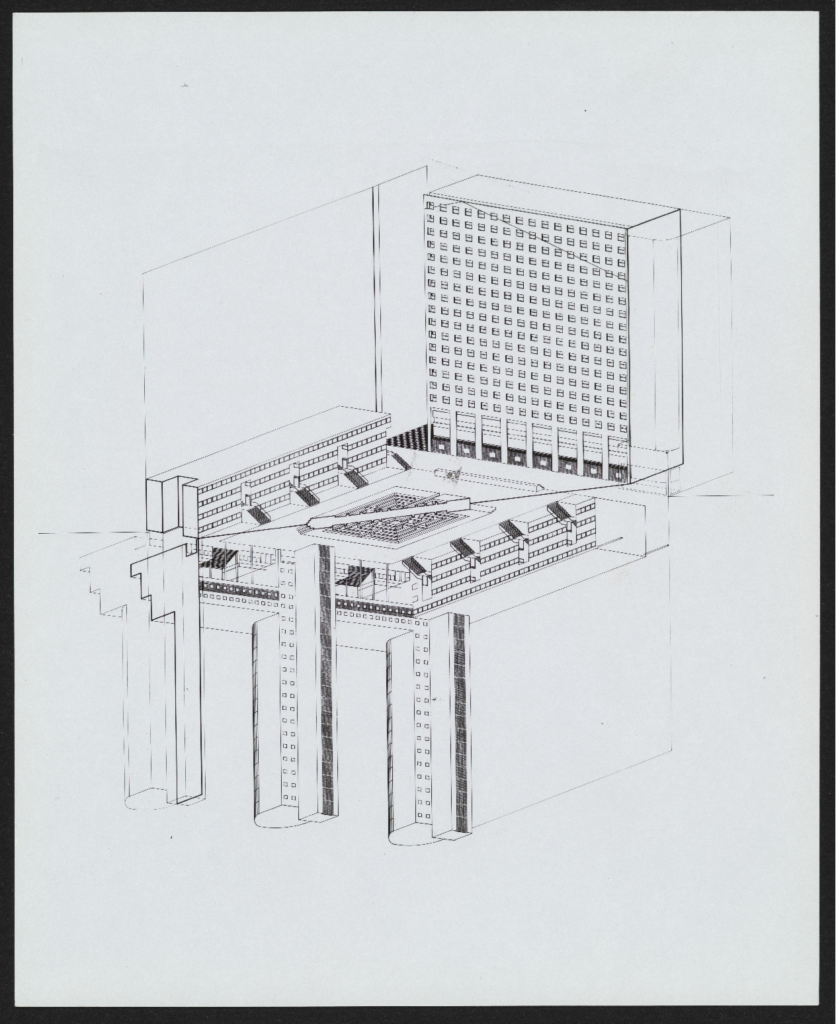
Axonometric (photographic print, 10″ x 8″)

Axonometric (photographic print, 10″ x 8″)
Collage (photographic print, 10″ x 8″)
fountain house [1975]
This house is a second residential home for a married couple in Southern California. This project presented, to an academic and sophisticated audience, the idea of architecture as a “polyphonic object.” It introduces a synthesis of modernity and classical vocabularies, bringing them together in a composition articulated by a technique of montage. Materials include glass, stucco, tile, marble, and a textile curtain.

1st floor [Floor Plan, Scale 1:50] (sepia diazotype on lightweight paper; 40″ x 29″)
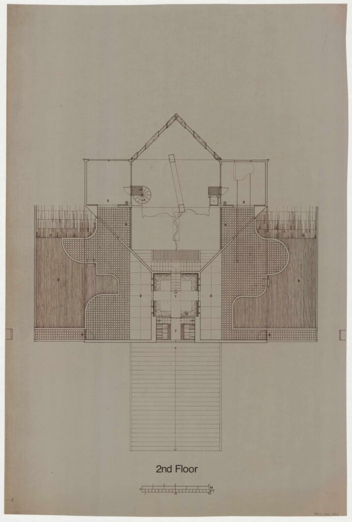
2nd Floor [Floor Plan, Scale 1:50] (sepia diazotype on lightweight paper; 25 1/4″ x 23 3/4″)
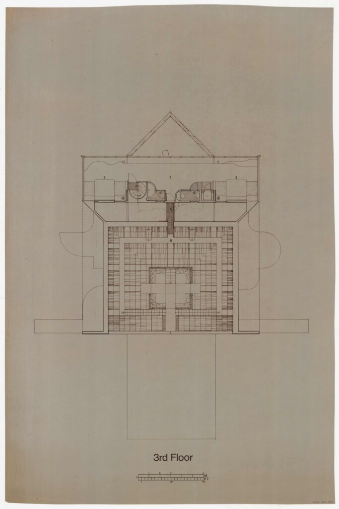
3rd Floor [Floor Plan, Scale 1:50] (sepia diazotype on lightweight paper; 35 1/2″ x 24″)

4th Floor [Floor Plan, Scale 1:50] (sepia diazotype on lightweight paper; 36″ x 23 1/2″)

Section A.A [Scale 1:50] (sepia diazotype on lightweight paper; 24″ x 35 1/2″)

Section B.B [Scale 1:50] (sepia diazotype on lightweight paper; 24″ x 35 1/2″)
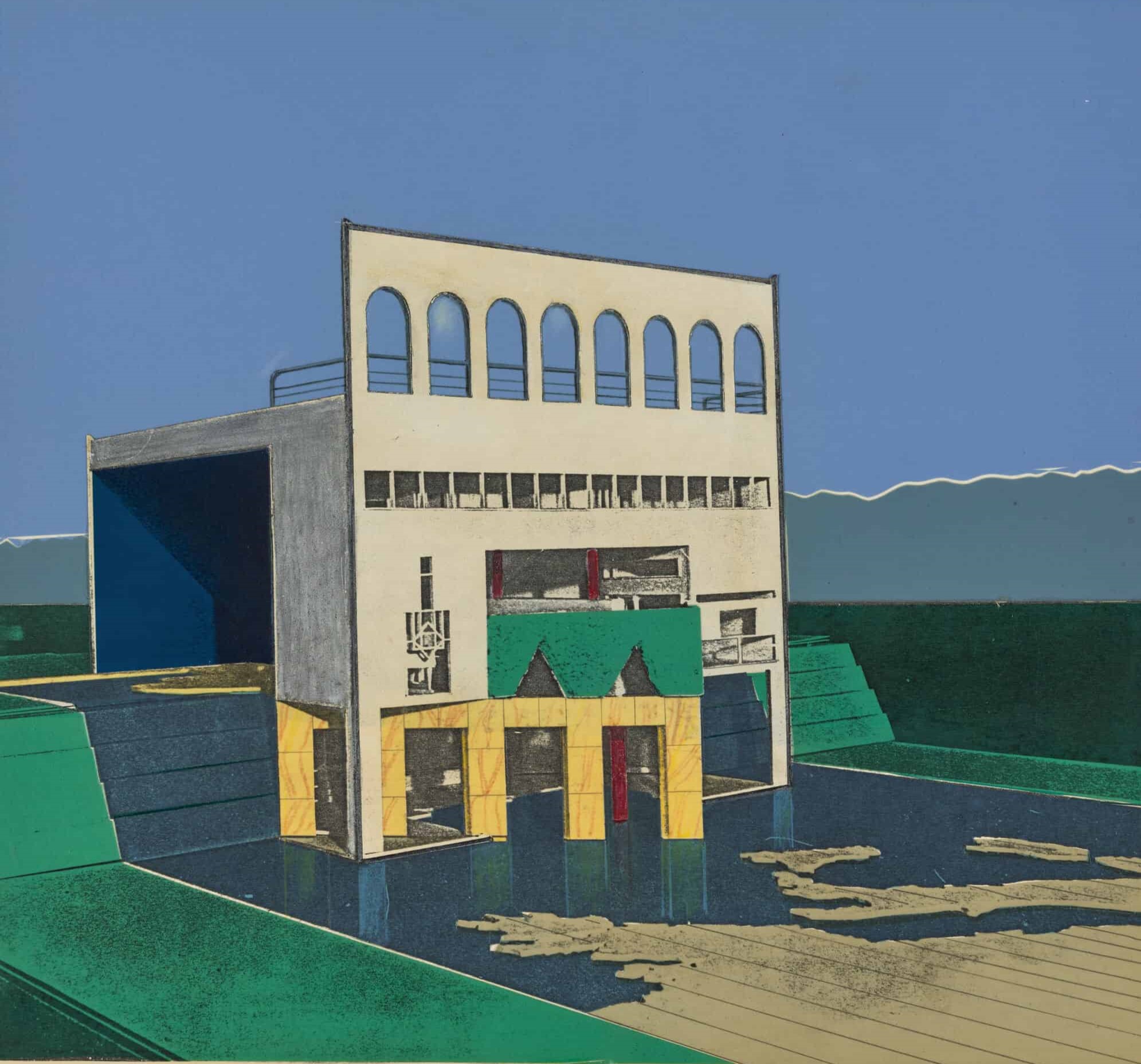
Exterior perspective (electrostatic copy with colored pencil and adhesive papers on vellum mounted on matboard card; 10 1/4″ x 11″)
dom new headquarters [1976]
This project was Rodolfo Machado and Jorge Silvetti’s entry for an invited competition for DOM’s new headquarters. The proposal consists of a square plan with an inscribed circle that translates formally to a rectangular base, cubic body, and a domed head. The program includes a presentation room, museum, attic, and flexible office space. External materials include anodized aluminum panels, glass windows, and a highly polished stainless-steel dome.
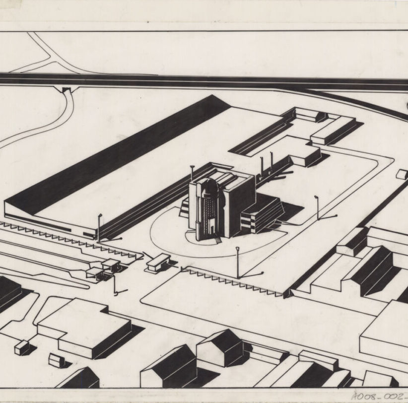
Exterior Bird’s Eye Perspective (black ink on mylar (matte front, gloss back); 7 1/2″ x 9″)
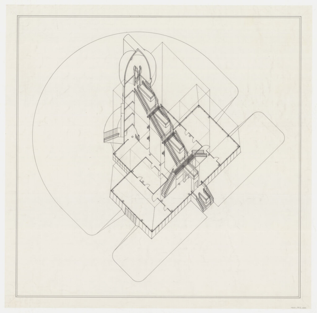
Building Section, Bird’s Eye Axonometric (black ink on mylar (gloss front, matte back); 31 1/2″ x 30″)
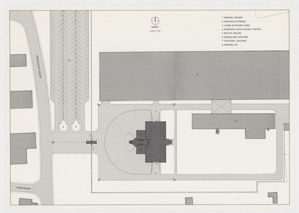
Site Plan (electrostatic copy on lightweight paper; 16 1/2″ x 23″)

Entrance Level Floor Plan [Scale: 1:200] and Seven Floor Plans [Scale: 1:500] (electrostatic copy on lightweight paper; 16 1/2″ x 23″)
country house [1977]
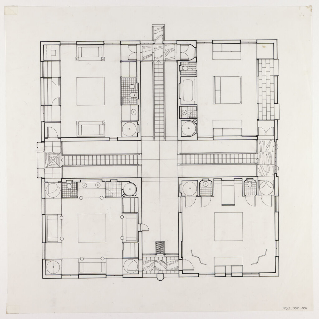
Country House, designed by Rodolfo Machado, is based upon an existing building: Villa Emo Capodilista (1570), in Montecchia, Selvazzano (Italy). This building, a manneristic piece of rigorous and self-conscious beauty, was understood to have the latent power for becoming an architectural “type.” It was then critically transferred to a new setting, the Piedmont region in Virginia. The novel design elaborates on two core themes: the notion of “room” (as opposed to “space”) as a legible entity; and the notion of an “attribute” that provides character to the function of the rooms.
The first-floor level of the house consists of four rooms and of four exterior gardens. Both rooms and gardens contain attributes that support their significance and that produce their specific character. These attributes are conceived as “architectural pieces” that provide a specific meaning to each room. On the second floor, each of the four bedrooms has its own variation. The equal size and shape of rooms provide a neutral background for the attributes. These attributes provide meaning to the rooms through their use as architectural devices.
Country House was included in the collective exhibition “Autonomous Architecture”, held at Harvard’s former Fogg Museum (now Harvard Art Museums).

1st Floor [Floor Plan, Scale 1:50] (black ink on mylar (matte); 37″ x 36″)
Second floor plan [Floor Plan, Scale 1:50] (electrostatic copy on mylar (matte front, gloss back); 18″ x 18″)

Mezzanine floor plan [Floor Plan, Scale 1:50] (electrostatic copy on mylar (matte front, gloss back); 18″ x 18″)

Front Elevation [Scale 1:50] (black ink on mylar (gloss front, matte back); 24″ x 36″)
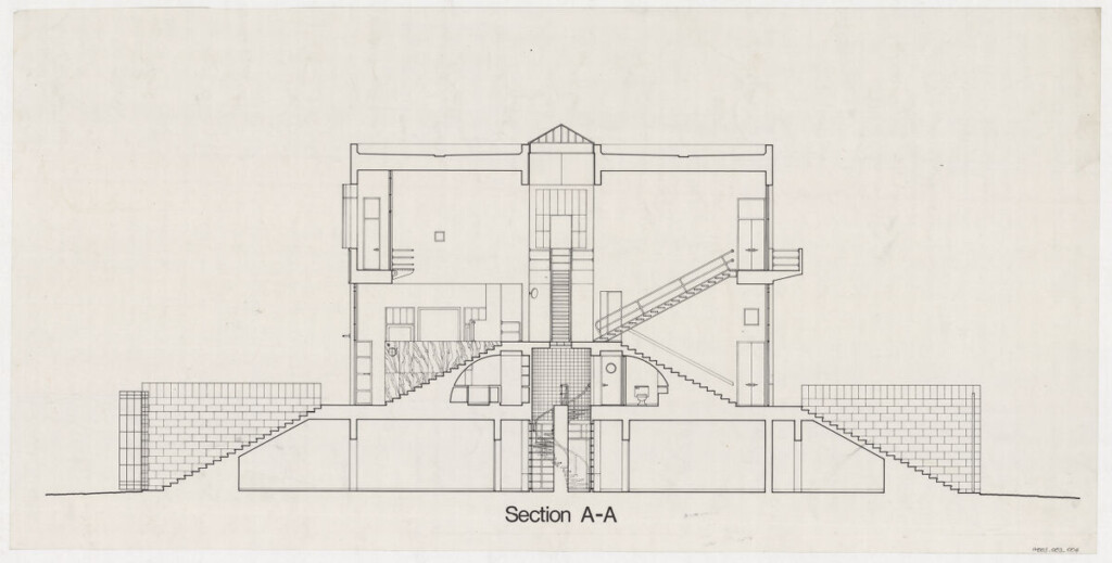
Section A·A (electrostatic copy on mylar (matte double sided); 18″ x 36″)

Dining Room [Interior perspective] (graphite pencil on strathmore; 15″ x 15″)

Library [Interior perspective] (graphite pencil on strathmore; 15″ x 15″)

Kitchen [Interior perspective] (graphite pencil on strathmore; 15″ x 16″)
Interior perspective (graphite pencil on strathmore; 29″ x 30″)
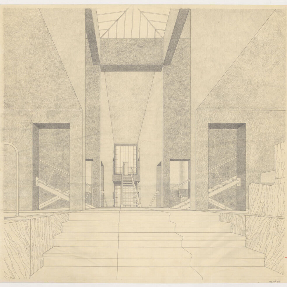
house on the island of djerba [1977]
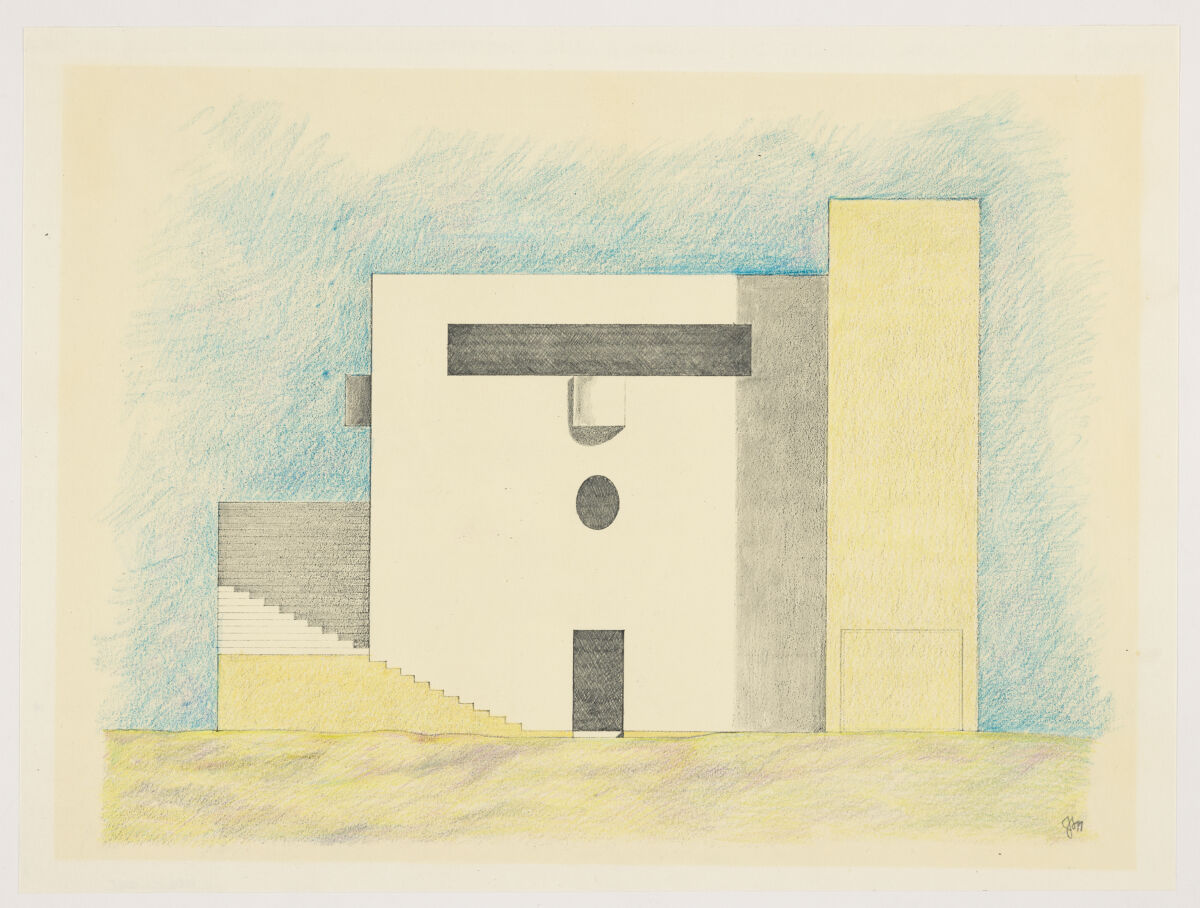
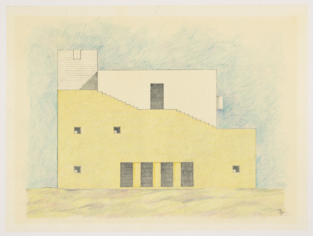
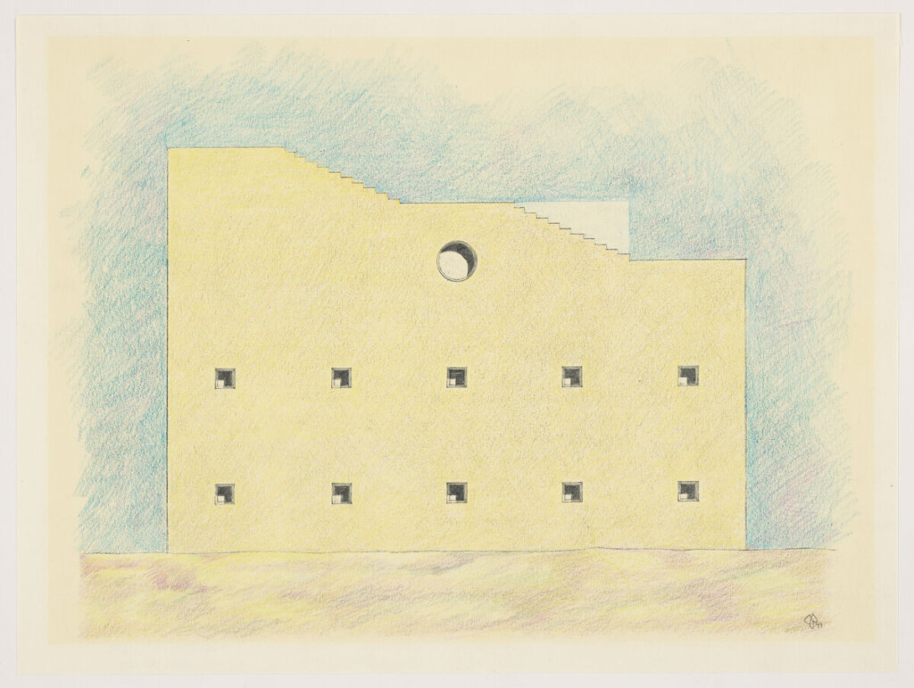
House on the Island of Djerba in Tunisia, designed by Jorge Silvetti, is a Mediterranean vacation home on a sandy beach on the north-west shore of the island. The project is based on a local vernacular type where connected rooms surround a courtyard. The layout consists of a three-meter-square grid with two main components: a cube and an exterior staircase. The exterior staircase, following building traditions of North Africa, wraps around and protects the cube. The cube, following the principles of European architecture, is classical in plan and proportion, and modern in appearance.
Inside are columns that rise two stories to support the master bedroom, which covers the courtyard; a metal stair connects the levels internally. The exterior staircase contains a loggia, music and dining rooms, kitchen, and service areas on the first floor; guest quarters on the second; and bath and dressing areas for the master bedroom on the third. Providing entry at every level of the cube, the exterior thick masonry staircase ascends to a terrace and belvedere overlooking the dunes and ocean.
House on the Island of Djerba was included in the collective exhibition “Autonomous Architecture”, held at Harvard’s former Fogg Museum (now Harvard Art Museums).
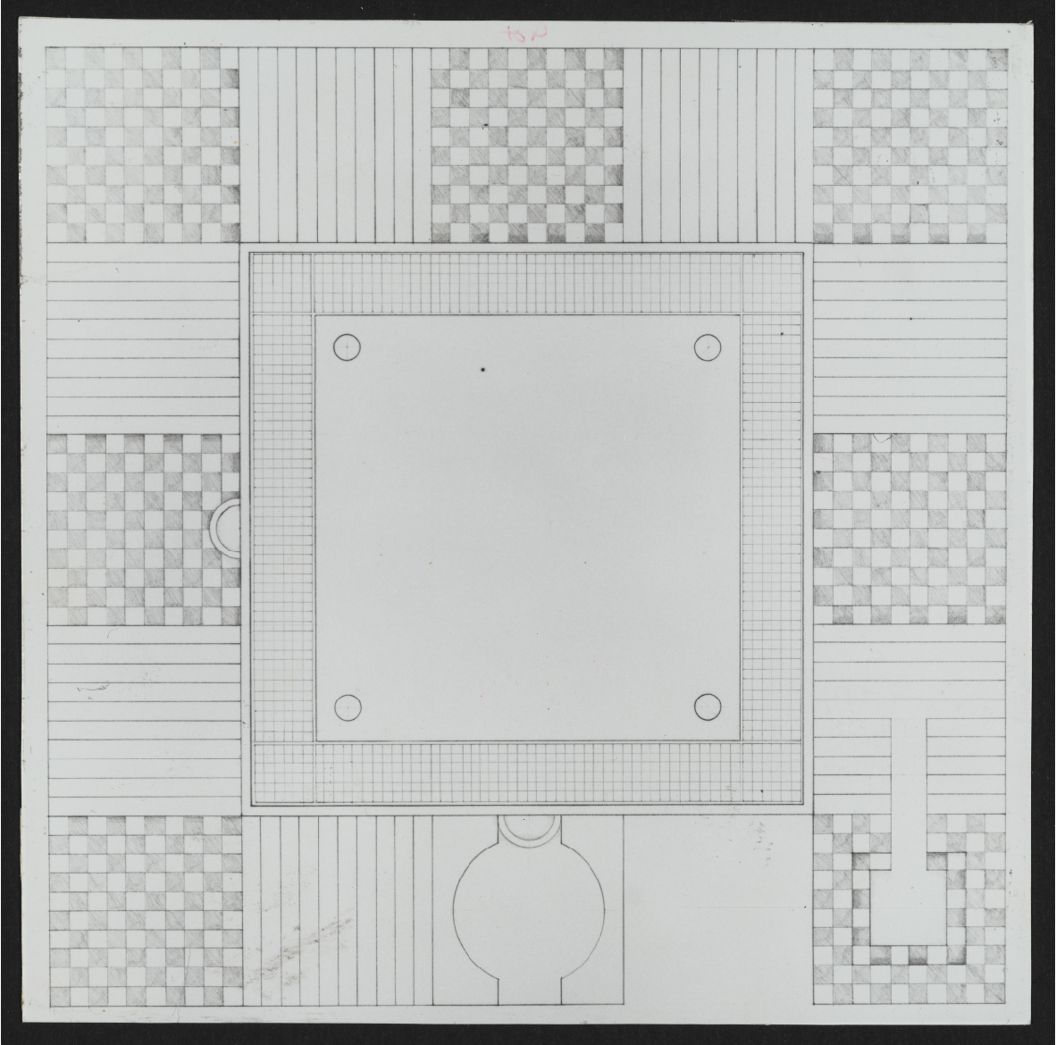
Floor Plan 01 (photographic print, 8″ x 8″)
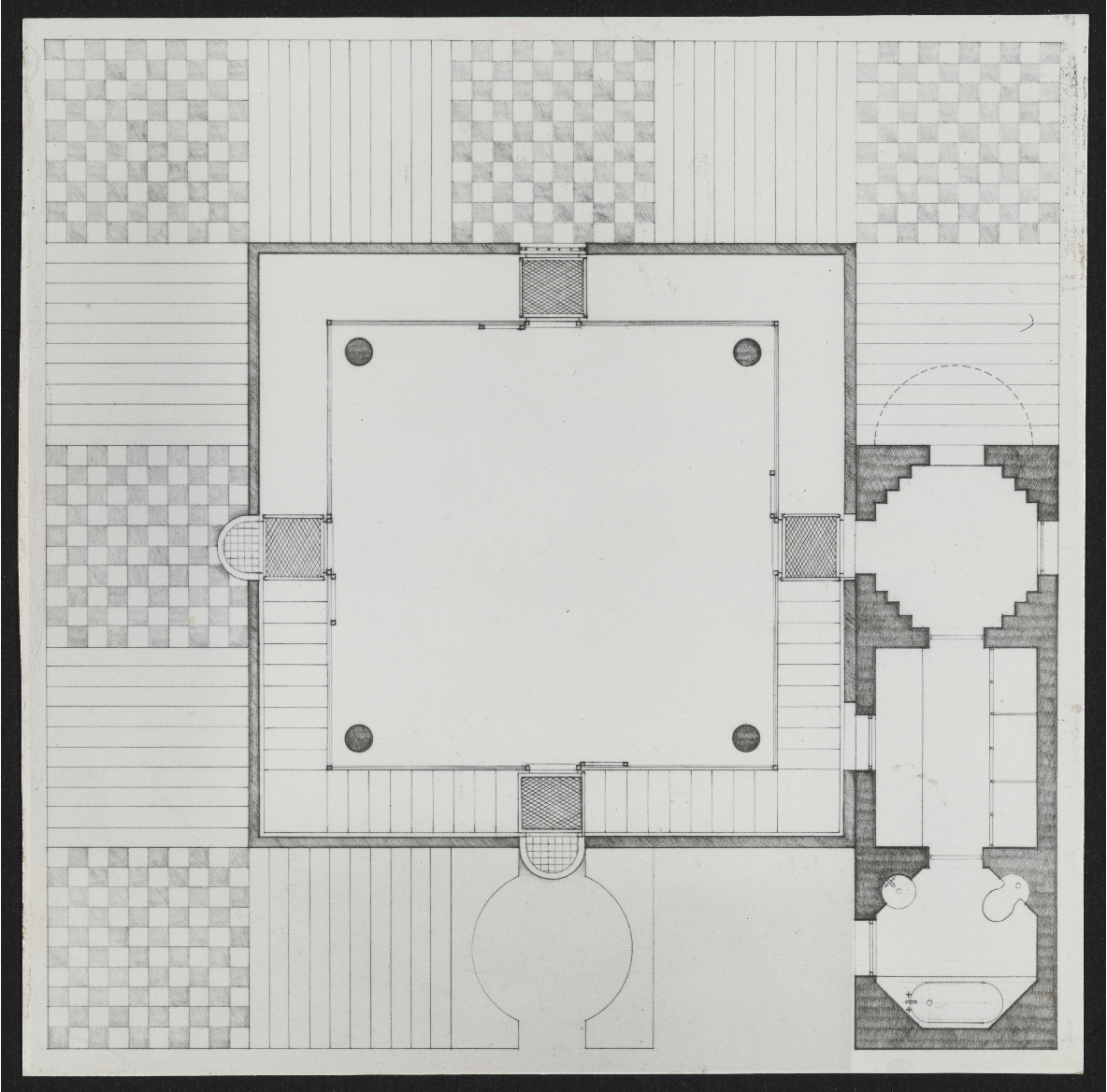
Floor Plan 02 (photographic print, 8″ x 8″)
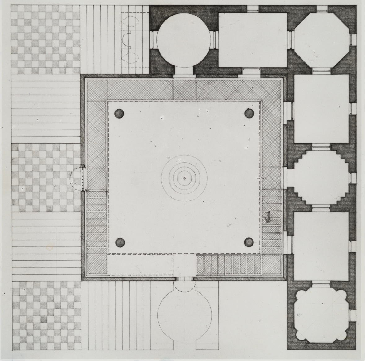
Floor Plan 03 (photographic print, 8″ x 8″)
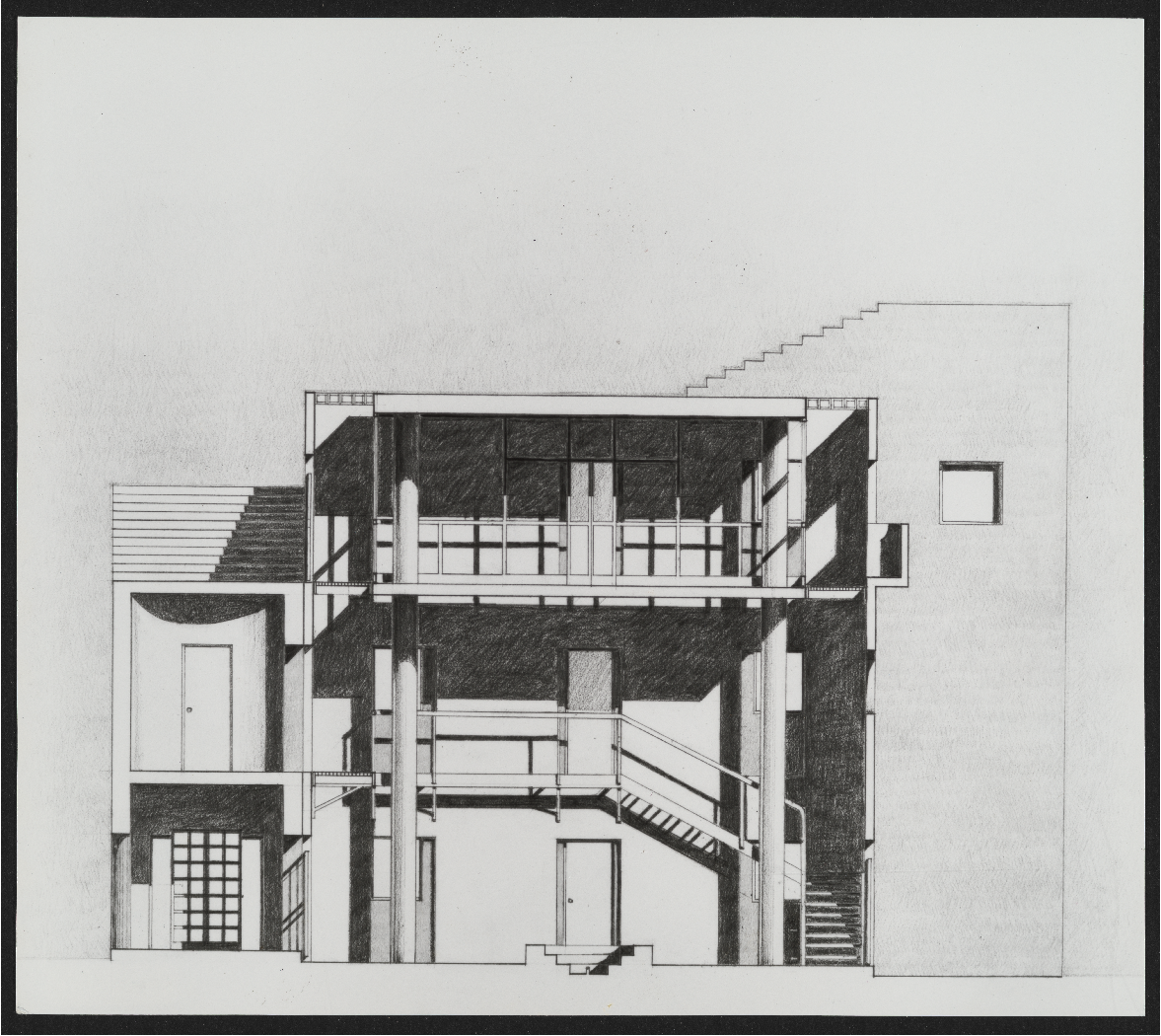
Section 01 (photographic print, 5″ x 5″)

Section 02 (photographic print, 5″ x 5″)
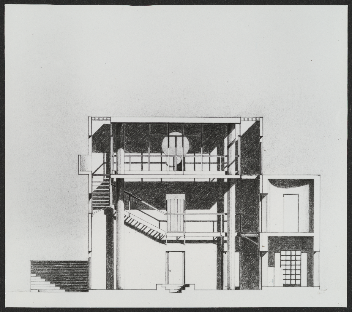
Section 03 (photographic print, 5″ x 5″)
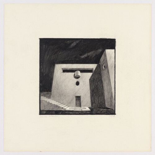
Exterior shaded perspective of facade 1 (black prismacolor on strathmore, 9″ x 9″)

Exterior shaded perspective of facade 2 (black prismacolor on strathmore, 9″ x 9″)
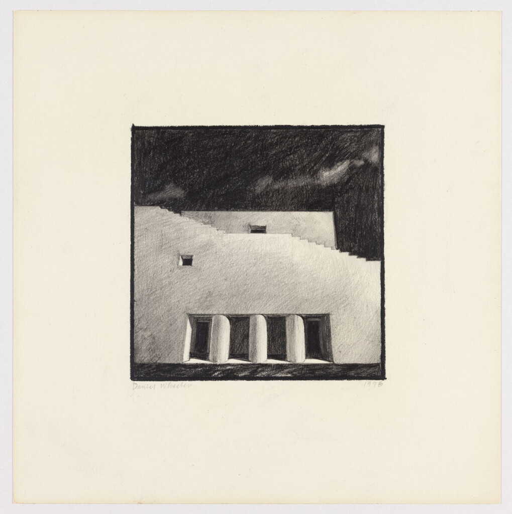
Exterior shaded perspective of facade 3 (black prismacolor on strathmore, 9″ x 9″)

Exterior shaded perspective of facade 4 (black prismacolor on strathmore, 9″ x 9″)
Façade 1 [Exterior elevation, signed by Jorge Silvetti] (electrostatic copy with graphite pencil and prismacolor on vellum; 14″ x 18″)

Façade 2 [Exterior elevation, signed by Jorge Silvetti] (electrostatic copy with graphite pencil and prismacolor on vellum; 14″ x 18″)
Façade 3 [Exterior elevation, signed by Jorge Silvetti] (electrostatic copy with graphite pencil and prismacolor on vellum; 14″ x 18″)
Façade 4 [Exterior elevation, signed by Jorge Silvetti] (electrostatic copy with graphite pencil and prismacolor on vellum; 14″ x 18″)
steps of providence [1978]
Steps of Providence was offered as a master plan to the Rhode Island School of Design (RISD) for the future development of their campus. An urban school, with a campus developed largely around the purchase of existing buildings, the campus results in an ad-hoc assemblage that needed a unifying character and the possibility of a pedestrian link between the riverfront and its historic district.
The urban design strategy includes a series of architectural and landscape interventions built around the theme of stairs. Memorial Steps, the monumental stair connecting the rear of the student union (Memorial Hall) with a public plaza overlooking the river become the new heart of the campus, while at the same time it offers itself as a public auditorium which is also the roof to a cafeteria.
The inherent quality of the site (a steep slope that rises from the river and downtown towards the historic district where RISD is located) helped envision the series of steps throughout the site that link buildings and facilitate circulation. Existing amorphous spaces are transformed into terraces, gardens, cloisters, and small sitting areas. The proposal also uses buildings to complement these public spaces. Some existing buildings along the route are remodeled and new structures include a dormitory that edges a stepped garden and a courtyard structure containing studios for graduate students.

The Steps of Providence General Plan (1″=40′)” [Site plan] (black ink, letraset and zipatone on lightweight mylar (matte front, gloss back); 48 1/4″ x 34″)
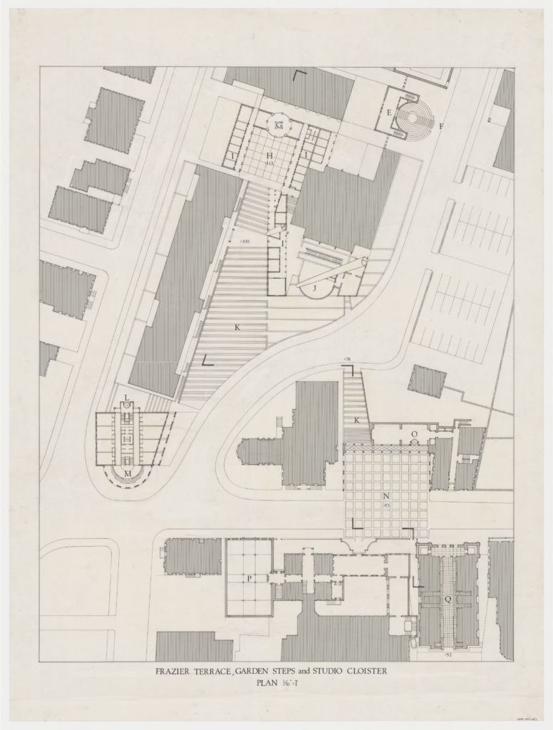
Frazier Terrace, Garden Steps, and Studio Cloister Plan. 1/16″ = 1′” [Site plan] (black ink, letraset and zipatone on lightweight mylar (matte front, gloss back); 48″ x 36″)
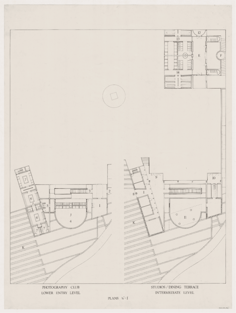
Plans 1/8″ [Three plans] (black ink and letraset on lightweight mylar (matte front, gloss back); 48″ x 36″)

Studio Cloister Upper Level 1/8″=1′” [Plan] (black ink and letraset on lightweight mylar (matte front, gloss back); 48″ x 36″)
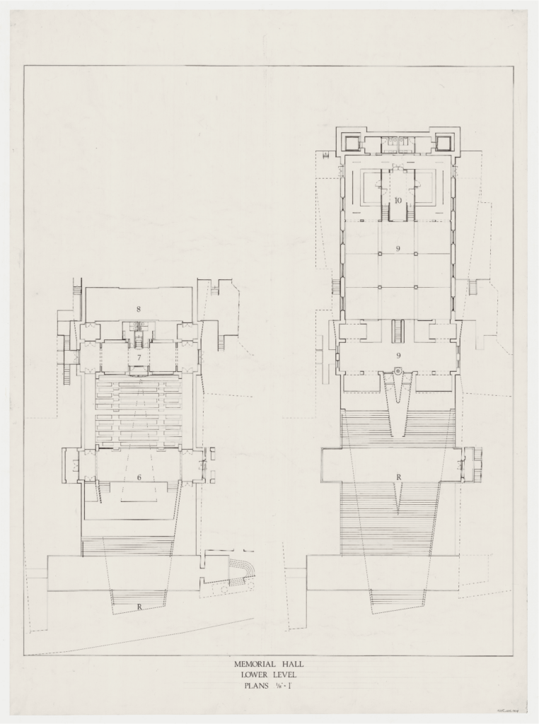
Memorial Hall Lower Level Plans 1/8″=1′” [Two plans] (black ink and letraset on lightweight mylar (matte front, gloss back); 48″ x 36″)
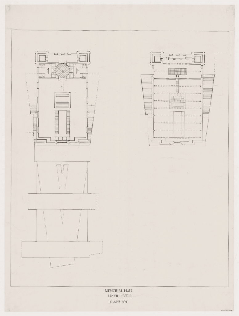
Memorial Hall Upper Level Plans 1/8″=1′” [Two plans] (black ink and letraset on lightweight mylar (matte front, gloss back); 48″ x 36″)

Woods-Gerry and the Green [Plan] [Scale: 1/16″=1′] (black ink wtih letraset and zipatone on mylar (gloss front, matte back); 21″ x 45 1/2″)
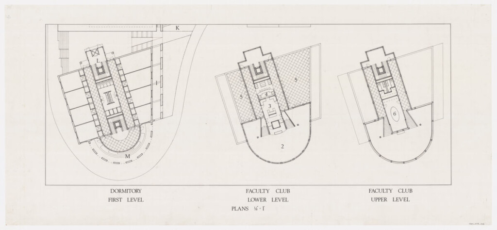
Dormitory First Level Plan, Faculty Club, Lower Level Plan Faculty Club Upper Level Plan (black ink wtih letraset on mylar (gloss front, matte back); 22″ x 48″)

Market Square-Memorial Steps [Section] (black ink with letraset on mylar (matte front, gloss back); 18″ x 43″)
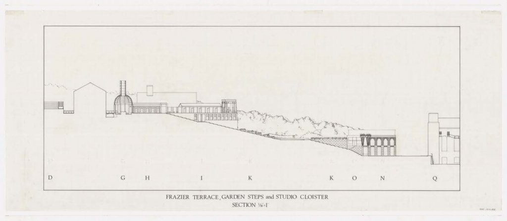
Frazier Terrace, Garden Steps and Studio Cloister [Section] [Scale: 1/16″=1′] (black ink wtih letraset on mylar (gloss front, matte back); 19 1/2″ x 48″)

Memorial Hall Facade [Exterior color shaded perspective] (sepia diazotype with prismacolor on vellum; 20″ x 22″)
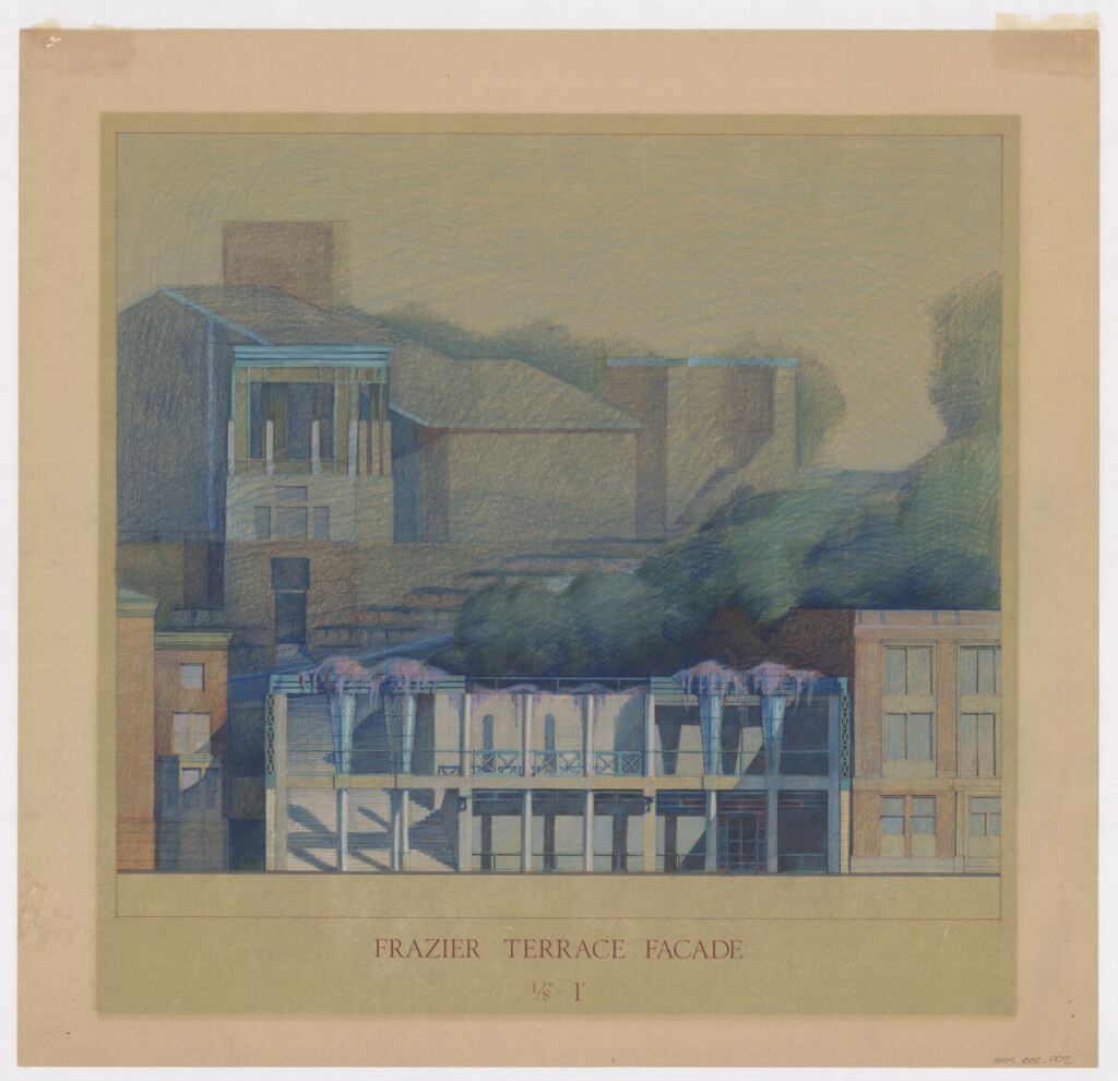
Frazier Terrace Facade [Exterior color shaded elevation] (sepia diazotype with prismacolor pencil on vellum; 26″ x 26″)

The Garden Steps [Exterior perspective] (black ink on mylar (matte front, gloss back); 23″ x 23″)

The Steps of Providence; Frazier Terrace” [Exterior Perspective] (black ink on mylar (gloss front, matte back); 23″ x 23″)
harvard faculty club [1979]
Interior remodeling, design of public areas and furnishing of Harvard University Faculty Club.

Elevation and plan, scale 1 1/2″ = 1′ (graphite on heavyweight paper; 30″ x 18″)
PROJECT INDEX
Additional projects by Jorge Silvetti and Rodolfo Machado completed in the 1970s.
Casa en Cuernavaca [1972]
Second family residence on the outskirts of Cuernavaca.
Project D’Architecture Nouvelle [1976]
Entry to the housing competition (in association with Diana Agrest and Mario Gandelsonas).
Walter Burley Griffin Memorial [1975]
Entry for the international competition for a memorial to Walter Burley Griffin, designer of Canberra.
Frances Loeb Library
Explore the archive further in the Finding Aid or plan your visit to Frances Loeb Library.